Communications
OI's main functionality is to provide operators with a method to see and modify information in PLCs. OI terminals can be configured to communicate with one or more PLCs through the Application -> Communications settings in OIB.
Communication Types
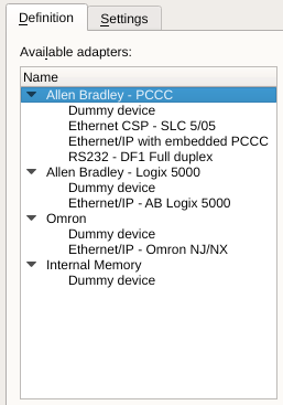
OI communication drivers are grouped by hardware types. Available hardware types are:
Allen Bradley PCCC
Alen Bradley Logix 5000
Omron
Internal Memory
Within the hardware types are specific drivers for communication protocols. While multiple hardware vendors claim to support the same protocol, we have found differences in the implementation of the protocols and provide separate drivers.
Internal Memory
One of the hardware types provide special capabilities. The internal memory adapter allows the creation of tags to be used entirely within the OI application. These allow interface interactions to be created that do not need configuration within the PLC and allow elimination of PLC logic strictly for those interaction.
The internal memory mimic's a PLC's data addresses. The address format for internal memory (dummy) device is N0:word/bit:
word = 0 .. (2^32 - 1) = 4 billion 16bit words
bit = 0 .. 15
The theoretical max size of internal memory is limited by the RAM available on the screen. Only memory used by existing tags is allocated from system memory.
Adapters
OI provides drivers for communicating with several different types of PLCs from Allen Bradley and Omron. OI also provides an Internal Memory adapter that can be used to create tags that do not need to be communicated to PLC's.
Dummy Device
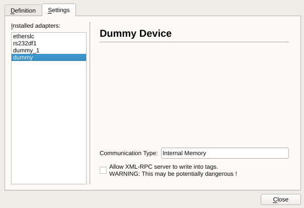
Dummy devices have no settings to edit as they act merely as tester devices for protocol types. The only variable here is the communication (or protocol) type which is set when installing adapters on the 'Definitions' page.
Each adapter provides a "Dummy device". This is a placeholder that can be used for testing without generating communication errors. These can be converted to other adapters within the same class by using the "Convert" function.
Tags referencing same memory address will reference the same data (works just like PLC data).
Warning
Tags referencing same memory address will reference the same data (works just like PLC data).
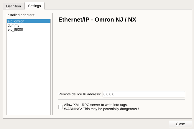
Ethernet/IP
Ethernet/IP adapters use the Ethernet/IP protocol to communicate with compatible PLC's. Currently Allen Bradley and Omron PLCs are compatible.
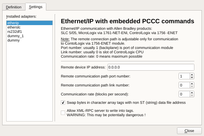
Ethernet CSP
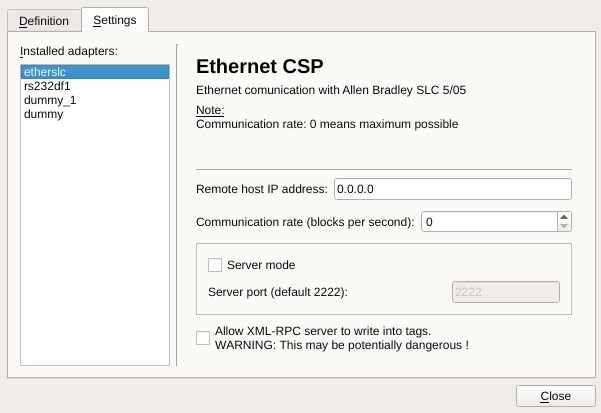
This adapter provides Ethernet CSP communication with Allen Bradley SLC 5/05 PLCs.
The DF1 protocol over Ethernet uses an SLC 5/05 adapter. The IP address and communication rate can be configured for this adapter.
RS232 DF1
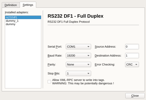
This adapter provides RS232 (serial) communication with Allen Bradley PLCs using the DF1 protocol. The following settings can be changed for this adapter:
Serial Port
Baud Rate
Parity
Stop Bits
Source Address
Destination Address
Error Checking
I/O Blocks
OI provides the ability to fine-tune communication with PLCs. Using the I/O Blocks settings is optional and provides a method to troubleshoot slow communications. OI automatically optimizes communications for tags being used, but in rare cases it can be helpful to specifically define how blocks are communicated.
All communication is sent in I/O blocks for controlling and monitoring input/output in a location remote from the processor.
Device Specific Details
Omron NJ/NX Ethernet/IP Communications
Only global variables with Network Publish property set in Sysmatic Studio to Publish Only or Input or Output are accessible from OI.
Bit addressing if integer types is not allowed. For example int_tag.3 addresses 4th bit of int_tag in AB Logix EIP driver, but this is not allowed in Omron.
If you want to write from OI into SINT or SUINT tag then OI tag type BitArray of length 8 must be used.
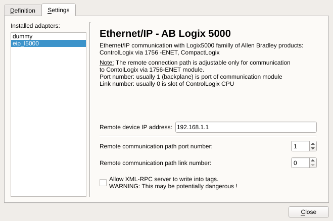
Ethernet/IP communication with AB Logix 5000 family of controllers
Logix5000 controllers store data in tags as opposed to SLC500 controllers which store data in data files. Logix5000 tags have these properties:
| Tag Property | Description |
|---|---|
name |
Identifies the data and is up to 40 characters in length (it cannot begin with or be a number - similar condition like in C programming language) |
scope |
Controller (global) or program (local) |
data type |
Defines the organization of the data |
The Logix5000 controller supports a large variety of data types:
| Data Type | Description |
|---|---|
atomic |
Bit, byte, word, double word, real, each of which stores a single value |
structure |
Grouping of different data types that function as single unit. Additionally to predefined structures there can be defined a user-defined structures in the controller. |
array |
Sequence of elements, each of which is the same data type. Data can be defined in up to three dimensions using atomic or structure data types. |
The following data types are directly accessible from OI-15
| Bit Length | Logix5000 Type | Direct OI type |
|---|---|---|
Bit |
BOOL |
Bit |
Bit Array |
BOOLEAN ARRAY (32 bit chunks) |
BitA (max length 32 bits - this means one chunk) |
8 bit integer |
SINT |
none * |
16 bit integer |
INT |
Int, Uint**, Bcd4*** |
32 bit integer |
DINT |
Dint, DUInt** |
32 bit float |
REAL |
Real |
Text up to 82 characters (8 bit) |
STRING-defined as structure of DINT LENGTH ASCII DATA[82] |
CharA (max length is 255) |
* 8 bit integer can be accessed as BitA of length 8
** signed integers are cast as unsigned ex. it means INT of value -1 is displayed as 65535
*** 16 bit integer can be interpreted in OI-15 in BCD4 format - it means maximum number is 9999
Examples of addressing syntax
| Tag Type | Address Syntax |
|---|---|
Atomic Tag - single tag |
tagName |
Atomic Tag - element of an array - 1 dimension |
tagName[x] |
Atomic Tag - element of an array - 2 dimensions |
tagName[x,y] |
Atomic Tag - element of an array - 3 dimensions |
tagName[x,y,z] |
Member of singular structure |
tagName.memberName |
Member inside single dimensioned array of structures |
tagName[x].memberName |
Member inside member of structure in two dimensioned array of structures |
tagName[x,y].memberName.memberName |
Global scope tag |
tagName |
Program scope tag |
PROGRAM:programName.tagName |
Accessing Local Tags within Logix5000
An example of the above syntax is addressing a local tag. Lets say we have a tag, MyTag, inside our program MyProgram. To access that tag's value within OI we'll use the address:
PROGRAM:programName.tagNameAccessing individual bits within Logix5000 tag
It is also possible to access individual bits or chunks of bits within Logix5000 tag. The address has the following format: tagName.bitNumber , tagName[x].memberName.bitNumber, etc…
BitNumber can be defined from 0 to 31.
Example
Example 1: You want to access single bit number 20 within DINT Logix5000 tag named “test” - you define an OI-15 tag of type Bit and set its address to test.20
Example
Example 2: You want to access higher 8 bits in INT Logix5000 tag named “test” - you define an OI-15 tag of type BitA of size 8 and set its address to test.8
Addressing STRING Logix5000 tag
Reading and writing of OI-15 tag of CharA type is expected via STRING Logix5000 tag. To define the address of OI-15 tag type CharA you only need to fill a name of STRING tag. Any other type is not supported. Maximum size of CharA tag is 82 characters, if you define a longer array an error is produced at runtime.
Addressing BOOLEAN ARRAY in Logix5000
Array of BOOLs is defined in 32bit chunks. Individual bits within that array are accessed differently than elements of other arrays. They are accessed by chunk position within array followed by bit position within that chunk.
Example
Example 3: To access bit number 45 in BOOLEAN ARRAY of length 64 named “test” you need to set the address test[1].14 (not test[45] which is the way how it is accessed in Logix5000 processor).
Communication with Logix5000 CPU is implemented using three CIP services
CIP Read Data
CIP Read Data is used for reading all OI-15 tags. OI-15 tag address specifies the name of a tag in Logix5000 controller.
CIP Write Data
CIP write data is used for writing CharA OI-15 tags. These tags are always written as STRING structure Logix5000 data type. OI-15 tag address specifies the name of whole STRING tag in the Logix5000 controller. If you specify tag with different type writing will not be successful.
CIP write data is also used for writing single bit OI-15 tags. It means tags of type Bit or BitArray with length 1. This service is used only when writing into Logix5000 tag of type BOOL. It is in case when the address of such an OI-15 tag does not point to an individual bit.
CIP Read Modify Write
CIP read modify write is used for writing all OI-15 tags except CharA and single bit (see CIP Write Data for exceptions). Data to write is defined as an array of OR masks followed by array of AND masks. The size of array can be 1,2,4,8,12 bytes. Within Logix5000 the tag data is read, the OR modification masks are applied then AND modification masks are applied, and finally the data is written back to the tag. The size of masks must be the same or smaller than the size of the data type being accessed.
Note 1
A problem in AB Logix5000 PLC family has been found, which caused the PLC to fault while program scoped tag is reading during PLC program download. Here is official response from Rockwell support : There are known issues with processors faulting in just such a case. These problems are being addressed in V16 which is due out in January of 2007. In the mean time, the suggestion is to alias a program scoped tags to controller scoped tags and read those instead. The problem has been verified with V16 version of ControlLogix firmware and V16 version of RS Logix 5000. The problem has been fixed in this version. So upgrade to this version solves that problem.
Note 2
In cases when OI-15 tag type is Bit or BitArray of length 1 and address does not contain bitNumber at the end, it is assumed that Logix5000 tag type is BOOL and CIP write service is used to modify the tag.
This condition had to be added due to a hidden feature in Logix5000 PLC which packs adjacent BOOL members of a structure as packs of eight. When Read Modify Write service was used to modify any of BOOL members within the pack, only the first member (the lowest bit) was modified each time.
XML-RPC
OI provides an XML-RPC server that can be used to serve tag information and values across the network and to scripts. The XML-RPC server can also modify tag values if the "Allow XML-RPC server to write into tags." is checked. This will allow HTTP and Shell scripts the ability to update tag values. We recommend only allowing this feature on a dedicated Internal Memory adapter for safety and security reasons. See the section on XML-RPC for more information.