Graphics
Static Text
| Property | Values | Description |
|---|---|---|
| name | string | Provide a name for the component. This can be helpful when using the "Used Components" tool in the tag editor. |
| description | string | A space to provide a description of the current component, useful for documenting intent. |
| geometry | x, y, width, height (ints) | Sets the visible geometry of the component: x and y from top left corner, and width/height. Editing these values can be useful when positioning/sizing finer than grid snap is needed. |
| hideTag | tag | When tag value is an integer other than zero, the component is not displayed on the screen. |
| color | color | Sets the drawing color: the line/outline color for Line, Circle and Rectangle components, and the text color for Static Text. |
| fillColor | color | Sets the color of the filled in area. |
| text | text | Sets the text that is displayed on the component. |
| textSize | int (pixels) | Sets the text size in pixels (clamped to 8-400; default 12). |
| textBold | true, false | When true, the text will be displayed in heavier type. |
| borderWidth | int (pixels) | Set the size of the border in pixels. 0 removes the border. |
| hAlignment | Left, Right, HCenter | Sets how the text is aligned on the component horizontally: left, right, or centered. |
| vAlignment | Top, Bottom, VCenter | Sets how the text is aligned on the component vertically: top, bottom, or center. |
| textWrap | NoWrap, WordWrap, WrapAnywhere | Controls line wrapping of displayed text: NoWrap (default), WordWrap (break at word boundaries), or WrapAnywhere (break mid-word when needed). |
| clickThrough | true, false | When true, click/touch events are passed through this element to elements underneath. This can be used to allow portions of an image to be buttons without needing a button to be displayed over that section of image. |
| filled | true, false | When true, the shape will be filled with the fillColor. |
Try it in the editor · property and state panels
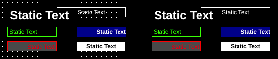
Static text should be thought of as a method of labeling or conveying unchanging information. Static text is static: it is constant and immovable while an application is running.
Static text does provide the ability to hide based on the value of the hideTag.
Image
| Property | Values | Description |
|---|---|---|
| name | string | Provide a name for the component. This can be helpful when using the "Used Components" tool in the tag editor. |
| description | string | A space to provide a description of the current component, useful for documenting intent. |
| geometry | x, y, width, height (ints) | Sets the visible geometry of the component: x and y from top left corner, and width/height. Editing these values can be useful when positioning/sizing finer than grid snap is needed. |
| hideTag | tag | When tag value is an integer other than zero, the component is not displayed on the screen. |
| foreColor | color | Sets foreground color (usually text). |
| backcolor | color | Sets background color. Images are allowed to set this to transparent to support images with alpha masks. |
| rotationTag | tag | Read tag – value defined in degrees the image is rotated around the rotationOrigin point. |
| offset | x, y (ints) | Two meanings by component: on Image and Multistate Indicator, the x/y distance the image is translated; on Dial, Knob, Fill Slide and Pointer Slide, a numeric value added to the tag value before display (displayed = value x scale + offset). |
| rotationOrigin | x, y (ints) | Sets rotation point of the component. Values are relative to the top-left of the component (0,0). |
| rotation | int | Number of degrees the image is rotated around rotationOrigin point. The rotation value will be applied to the component when OI screen is loaded and rotationTag is missing, or before rotationTag value is read from PLC. This property is useful for testing rotated images in OIB during development. Default value is 0. |
| clickThrough | true, false | When true, click/touch events are passed through this element to elements underneath. This can be used to allow portions of an image to be buttons without needing a button to be displayed over that section of image. |
| image | image | The image that will be displayed. Images are selected from the applications image collection. |
| monoImage | true, false | When true, converts the image to black and white. |
| scaledImage | true, false | When true, scales the image to the size of the component. When false, the image is painted 1:1 scale, and any pixels outside the component area are not painted. |
| xClickWriteTag | tag write | When set, the x position relative from the top-left corner of any touch events on this component will be written to this tag. Only the touch start event is written (the position where the touch is released and positions during drag are not written). |
| yClickWriteTag | tag write | When set, the y position relative from the top-left corner of any touch events on this component will be written to this tag. Only the touch start event is written (the position where the touch is released and positions during drag are not written). |
| zoomX | float | Sets the width of the component to the width of the image times this value. This allows fitting images larger than the screens display resolution onto the screen. |
| zoomY | float | Sets the height of the component to the height of the image times this value (result clamped to 5-2000 pixels). |
| transparentFore | true, false | When true, the part of the image that would be considered the fore-color when converted to black and white (monoImage) is set to transparent. Setting transparentBack to true will change this value to false. |
| transparentBack | true, false | When true, the part of the image that would be considered the back-color when converted to black and white (monoImage) is set to transparent. Setting transparentFore to true will change this value to false. |
| xOffsetTag | tag | Updates the image x position by this value in screen pixels. |
| yOffsetTag | tag | Updates the image y position by this value in screen pixels. |
Try it in the editor · property and state panels
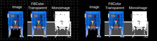
Image components provide a component that displays an image within its bounds. The image component supports a variety of image formats, including formats with alpha channels, and provides tools to adjust the display of images.
Info
Please resize your images to a resolution close to the size they will be displayed. We often see very large images (4032x3024) used for components that are displayed in 600x400 pixels. Using oversized images can degrade the performance of OI, increase load time of screens, and results in unnecessarily large OI files.
For example, a 4032x3024 picture can be 2mb in size whereas a 600x400 picture is usually around 100kb - a 20x difference in file sizes.
OIB versions later than OIB 1.11 Dec 2020 include tools to resize images.
Note
Offset is applied relative to the top-left corner.
Then rotation is applied around the rotationOrigin relative to the top-left image corner.
Image components use images from the application's image library. When an image is added to the library, it is copied to the application's directory and renamed to pre-pend the application name.
OI supports common image formats including PNG, BMP, JPEG, GIF, TIFF, WEBP, SVG, PBM, PGM, PPM, XPM, and XBM. Alpha channels (transparency) are supported and can be seen by changing backColor to transparent. The transparentFore and transparentBack properties also work on color images; with monoImage set to true the foreground/background can additionally be recolored (see below).
Tip
Images by default are given black backgrounds. If you have transparency in your images, set the backColor to transparent to see those.
Warning
When using transparency, fully transparent parts of the images will pass clicks through to lower elements regardless of clickThrough property.
Rotation
Images support dynamic rotation by using the rotation tag. Currently, image components only display the image within the bounds of the component - so if the image rotates outside this bound parts of the image will not be displayed.
Warning
Rotation behavior and rendering may change in future releases.
monoImage
The 'monoImage' property converts the image to a monochrome image. When true, the foreground and background colors of the monochrome image can be substituted, and transparentFore/transparentBack apply to the converted image.
xClickWriteTag, yClickWriteTag
The xTag and yTag properties provide a way of feeding inputs back relative to the image. When a position on the image is touched, the x and y position of the touch is written to xClickWriteTag and yClickWriteTag. The coordinates are relative to the component's top-left corner (not the image, which may be offset or rotated).
Image Resizing Tools
Images can be resized within OIB by clicking the Resize... button for the image in the image library. This tool provides inputs to specify the new size of the image and also reports the size of the largest component using this image.
This tool modifies the files directly and cannot be undone.
Warning
Resizing images modifies the image files directly and cannot be undone.
Rectangle
| Property | Values | Description |
|---|---|---|
| name | string | Provide a name for the component. This can be helpful when using the "Used Components" tool in the tag editor. |
| description | string | A space to provide a description of the current component, useful for documenting intent. |
| geometry | x, y, width, height (ints) | Sets the visible geometry of the component: x and y from top left corner, and width/height. Editing these values can be useful when positioning/sizing finer than grid snap is needed. |
| hideTag | tag | When tag value is an integer other than zero, the component is not displayed on the screen. |
| color | color | Sets the drawing color: the line/outline color for Line, Circle and Rectangle components, and the text color for Static Text. |
| fillColor | color | Sets the color of the filled in area. |
| clickThrough | true, false | When true, click/touch events are passed through this element to elements underneath. This can be used to allow portions of an image to be buttons without needing a button to be displayed over that section of image. |
| filled | true, false | When true, the shape will be filled with the fillColor. |
| lineWidth | int (pixels) | Sets the width of the line in pixels. |
Try it in the editor · property and state panels
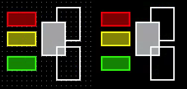
Rectangle components draw a static rectangle on the screen. The border and fill properties can be adjusted as needed.
Circle
| Property | Values | Description |
|---|---|---|
| name | string | Provide a name for the component. This can be helpful when using the "Used Components" tool in the tag editor. |
| description | string | A space to provide a description of the current component, useful for documenting intent. |
| geometry | x, y, width, height (ints) | Sets the visible geometry of the component: x and y from top left corner, and width/height. Editing these values can be useful when positioning/sizing finer than grid snap is needed. |
| hideTag | tag | When tag value is an integer other than zero, the component is not displayed on the screen. |
| color | color | Sets the drawing color: the line/outline color for Line, Circle and Rectangle components, and the text color for Static Text. |
| fillColor | color | Sets the color of the filled in area. |
| clickThrough | true, false | When true, click/touch events are passed through this element to elements underneath. This can be used to allow portions of an image to be buttons without needing a button to be displayed over that section of image. |
| filled | true, false | When true, the shape will be filled with the fillColor. |
| lineWidth | int (pixels) | Sets the width of the line in pixels. |
Try it in the editor · property and state panels
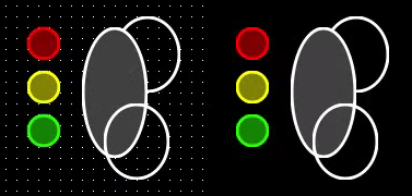
Ellipse components draw a static circle or ellipse on the screen. The border and fill properties can be adjusted as needed.
Line
| Property | Values | Description |
|---|---|---|
| name | string | Provide a name for the component. This can be helpful when using the "Used Components" tool in the tag editor. |
| description | string | A space to provide a description of the current component, useful for documenting intent. |
| hideTag | tag | When tag value is an integer other than zero, the component is not displayed on the screen. |
| color | color | Sets the drawing color: the line/outline color for Line, Circle and Rectangle components, and the text color for Static Text. |
| clickThrough | true, false | When true, click/touch events are passed through this element to elements underneath. This can be used to allow portions of an image to be buttons without needing a button to be displayed over that section of image. |
| lineWidth | int (pixels) | Sets the width of the line in pixels. |
| beginPoint | x, y (ints) | X/Y coordinates of the line's begin point, editable as x and y sub-rows in the property editor. |
| endPoint | x, y (ints) | X/Y coordinates of the line's end point, editable as x and y sub-rows in the property editor. |
| beginArrow | true, false | When true, an arrow will be displayed at the beginning point. |
| endArrow | true, false | When true, an arrow will be displayed at the ending point. |
| beginXTag | tag | Tag that dynamically sets the X coordinate of the line's begin point. At startup OI writes the design-time coordinate to this tag, then follows the tag's value. |
| beginYTag | tag | Tag that dynamically sets the Y coordinate of the line's begin point. At startup OI writes the design-time coordinate to this tag, then follows the tag's value. |
| endXTag | tag | Tag that dynamically sets the X coordinate of the line's end point. At startup OI writes the design-time coordinate to this tag, then follows the tag's value. |
| endYTag | tag | Tag that dynamically sets the Y coordinate of the line's end point. At startup OI writes the design-time coordinate to this tag, then follows the tag's value. |
Try it in the editor · property and state panels
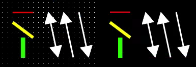
Line components draw a static line on the screen.
Dynamic Lines
End points of lines can be changed dynamically by PLCs through the beginX, beginY, endX, and endY tags. The initial values as set in the OIB application are first written to the tags, then any changes will update the line's position on the screen.
The coordinates are in screen space and match as the values would in the beginPoint and endPoint attributes.